Geo Fixture
General
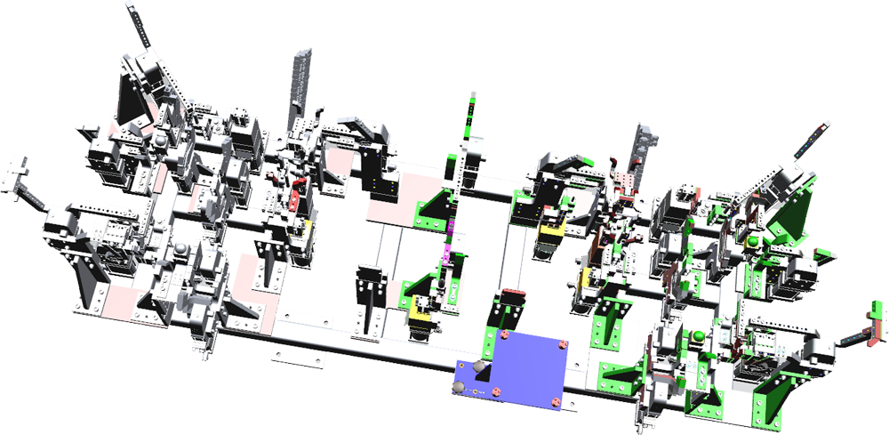
There are two (2) Geo Fixtures mounted on top of the turntable located in the 2V12 Rear Wall Header & Door Ring RH Cell. The Geo Fixtures perform the holding of parts during robot pick, place, and securing parts while robot(s) perform the required welding operations. The fixtures can be simple or complex based on the parts to be processed.
To secure the parts during operation, the Geo Fixture features multiple clamps that grip and secure the part, preventing any movement from occurring. Additionally, the Geo Fixture features rough locators and locating pins to help assist the operator in verifying the part is loaded properly.
Major Components
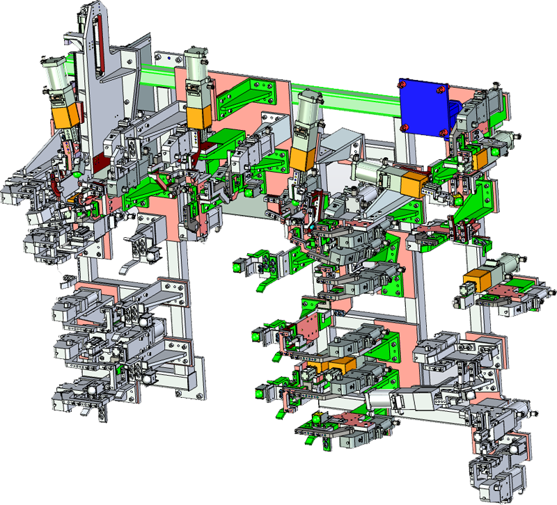
The Geo Fixture features the following components.
| Item | Description | Function |
|---|---|---|
| A | Clamps | The Tunkers clamps actuate via pneumatic cylinder and secures the part into position while welding Operations are preformed. |
| B | Rough Locators | To ensure parts are properly loaded onto the Geo Fixture, the Rough Locators provide a way for the operator to align and place the parts into the fixture. |
| C | Locating Pins | The Locating Pins on the Geo Fixture allow for the accurate and controlled placement of the parts. When the operator loads the part onto the Geo Fixture, the part must have each locating pin inserted into the locating hole. |
Geo Fixture DRRH-010-T1 (GEOF1) Sequence of Operations
The Sequence of Operations for Geo Fixture DRRH-010-T1 (GEOF1) are in a summarized format for the purpose of the Interactive Electronic Technical Reference Manual (IETM).
| No | Step |
|---|---|
| 1 | Operator obtains lift assist. |
| 2 | Operator obtains Door Ring Assembly. |
| 3 | Operator places Door Ring Assembly in dunnage. |
| 4 | Operator disposes of lift assist. |
| 5 | Operator obtains part Hinge Reinforcement (6426) and A Pillar (4748). |
| 6 | Operator walks through light screen to fixture 010-T1 and loads A Pillar (6426) and A Pillar (4748). |
| 7 | Operator walks to totes and obtains part (5728). |
| 8 | Operator loads part (5728) to fixture. |
| 9 | Operator obtains lift assist. |
| 10 | Operator obtains A Pillar (4748) from dunnage. |
| 11 | Operator loads A Pillar (4748) to fixture. |
| 12 | Operator walks to palm button and depresses palm button. |
| 13 | Operator walks to HDR dunnage. |
| 14 | Geo fixture clamps close (UQ4.1, UQ4.2, UQ4.3, UQ4.4, UQ4.5, UQ4.6, UQ5.1, UQ5.2, UQ5.3, UQ6.1). |
| 15 | Shot pin (UQ2.1) retracts. |
Geo Fixture DRRH-010-T2 (GEOF2) Sequence of Operations
The Sequence of Operations for Geo Fixture DRRH-010-T2 (GEOF2) is listed below are listed below in a summarized format for the purpose of the Interactive Electronic Technical Reference Manual (IETM).
| No | Step |
|---|---|
| 1 | Operator walks to fixture. |
| 2 | Operator loads two (2) Baffles (5717) to 010-T2. |
| 3 | Operator walks to part bin and obtains Part Cross Meb (1995). |
| 4 | Operator walks to fixture and loads Part Cross Meb (1995) to fixture. |
| 5 | Operator obtains one Reinf HDR (0872) and one Reinf HDR (0870) from parts bins. |
| 6 | Operator returns to fixture and loads both Reinf HDR (0870 and 0872) to fixture). |
| 7 | Operator walks to part bin and obtains two (2) Tie PLT (6976). |
| 8 | Operator loads parts two (2) Tie PLT (6976) to fixture. |
| 9 | Operator walks to part bin and obtains one Cross Meb (1994). |
| 10 | Operator returns to fixture and loads one Crooss Meb. (1994). |
| 11 | Operator walks to palm button and depresses palm button. |
| 12 | Geo fixture 010-T2 clamps close (UQ3.1, UQ3.2, UQ3.3, UQ3.4, UQ3.5, UQ3.6, UQ4.1, UQ4.2, UQ4.3, UQ4.4, UQ4.5, UQ4.6, UQ5.1, UQ5.2, UQ5.3, UQ5.4, UQ6.1, UQ6.2, UQ6.3, UQ6.4, UQ7.1, UQ7.2, UQ8.1, UQ8.2, UQ9.1, UQ9.2, UQ10.1, UQ10.2). |