Cell Power Down Procedure
Cell Power Down Notation
The following procedure covers the power down of the 2V12 Rear Wall Header & Door Ring RH Cell. This procedure assumes that the 2V12 Rear Wall Header & Door Ring RH Cell is currently cycling in Automatic Mode of operation.
Allow only personnel with appropriate training and experience to operate or service the equipment. The use of untrained or inexperienced personnel to operate or service the equipment can result in injury, including death, to themselves and others, and/or damage to the equipment.
Step 1: Main Operator Panel (MOP)
- Place the two-position selector switch into the "MAN" position.

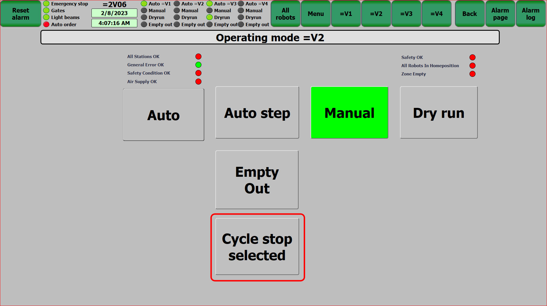
Step 2: Main Operator Panel (MOP) - Cycle Stop
- From the Main Operator Panel (MOP), press the "Menu" button. This will redirect users to the Operating Mode Screen.
- From the Operating Mode Screen, press the "Cycle Stop" function button. The equipment within the cell will finish its current cycle and all station equipment will return to the Home position.
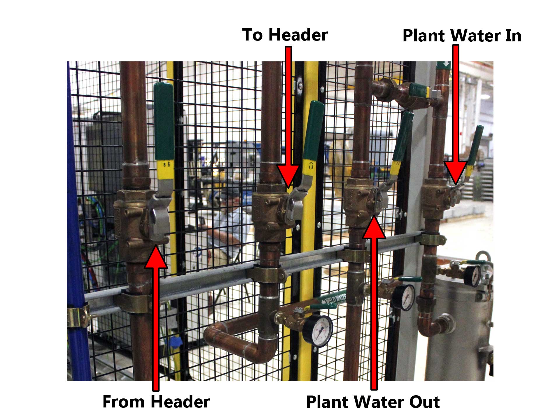
Step 3: Water System
- Place the Plant Water In Ball Valve to the "CLOSED" position.
- Place the To Header Ball Valve to the "CLOSED" position.
- Place the From Header Ball Valve to the "CLOSED" position.
- Place the Plant Water Out Ball Valve to the "CLOSED" position.
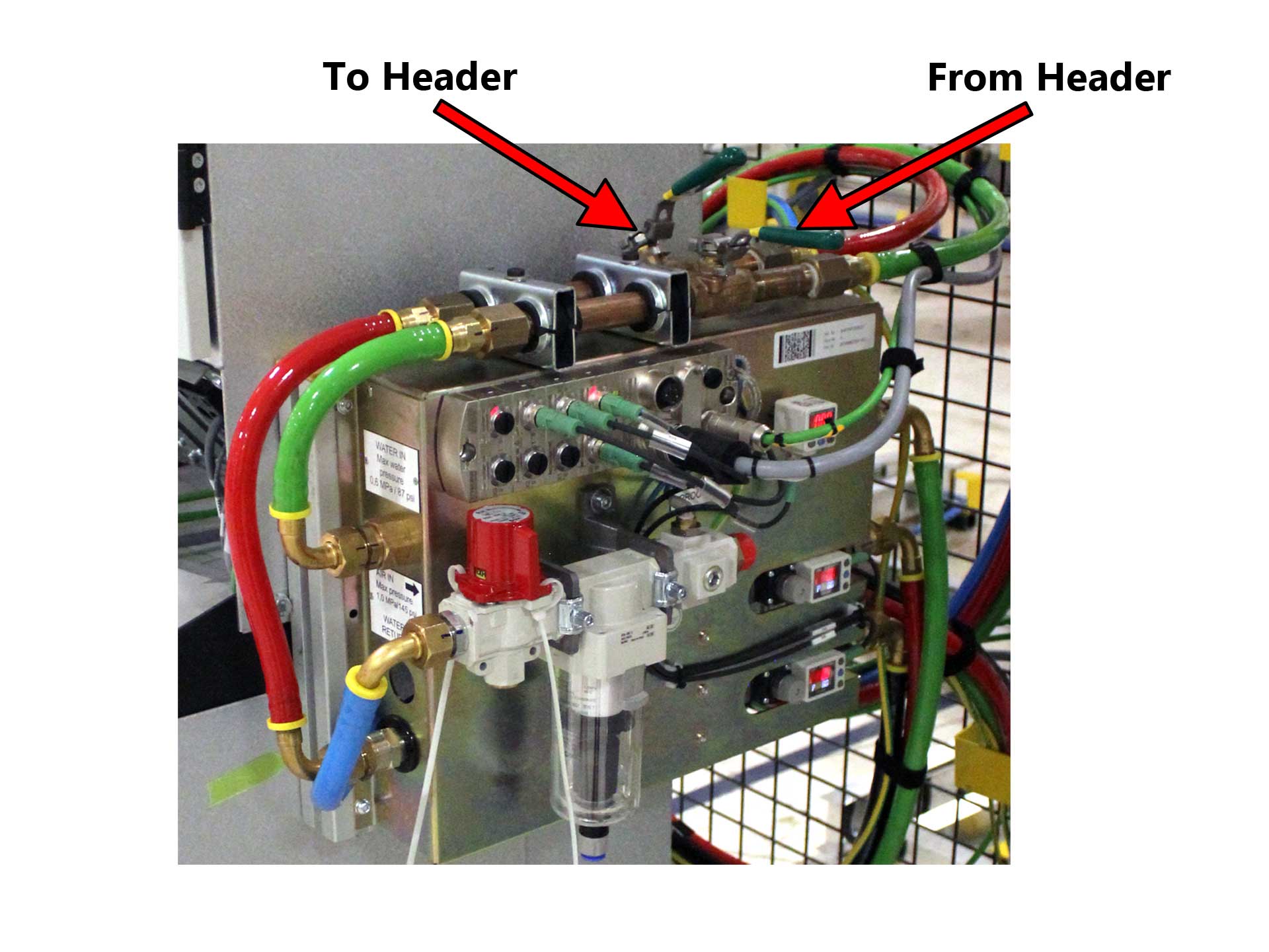
- On each ABB Weld Controller, place the To Header and From Header Ball Valves to the "CLOSED" position.
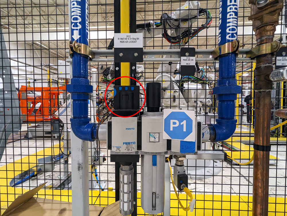
Step 4: Main Air Distribution Panel
- At the Main Air Distribution Panel, rotate the safety lockout valve to the "CLOSED" position.
- On the pressure regulator unit, verify there is a zero (0) reading on the pressure regulator unit.
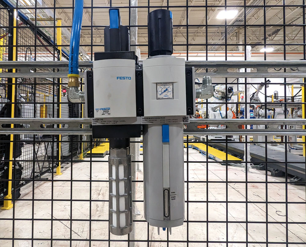
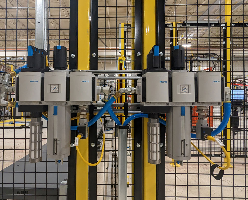
Step 5: Ancillary Air
- At the Station Level Air Distribution Panels (or Ancillary Air Panels) place the Safety Lockout Valve to the "CLOSED" position.
- On the pressure regulator or digital pressure switch, verify the incoming air is set to the safe, required operating pressure.
- Ancillary air panels are located throughout the system for the turntables and robots.

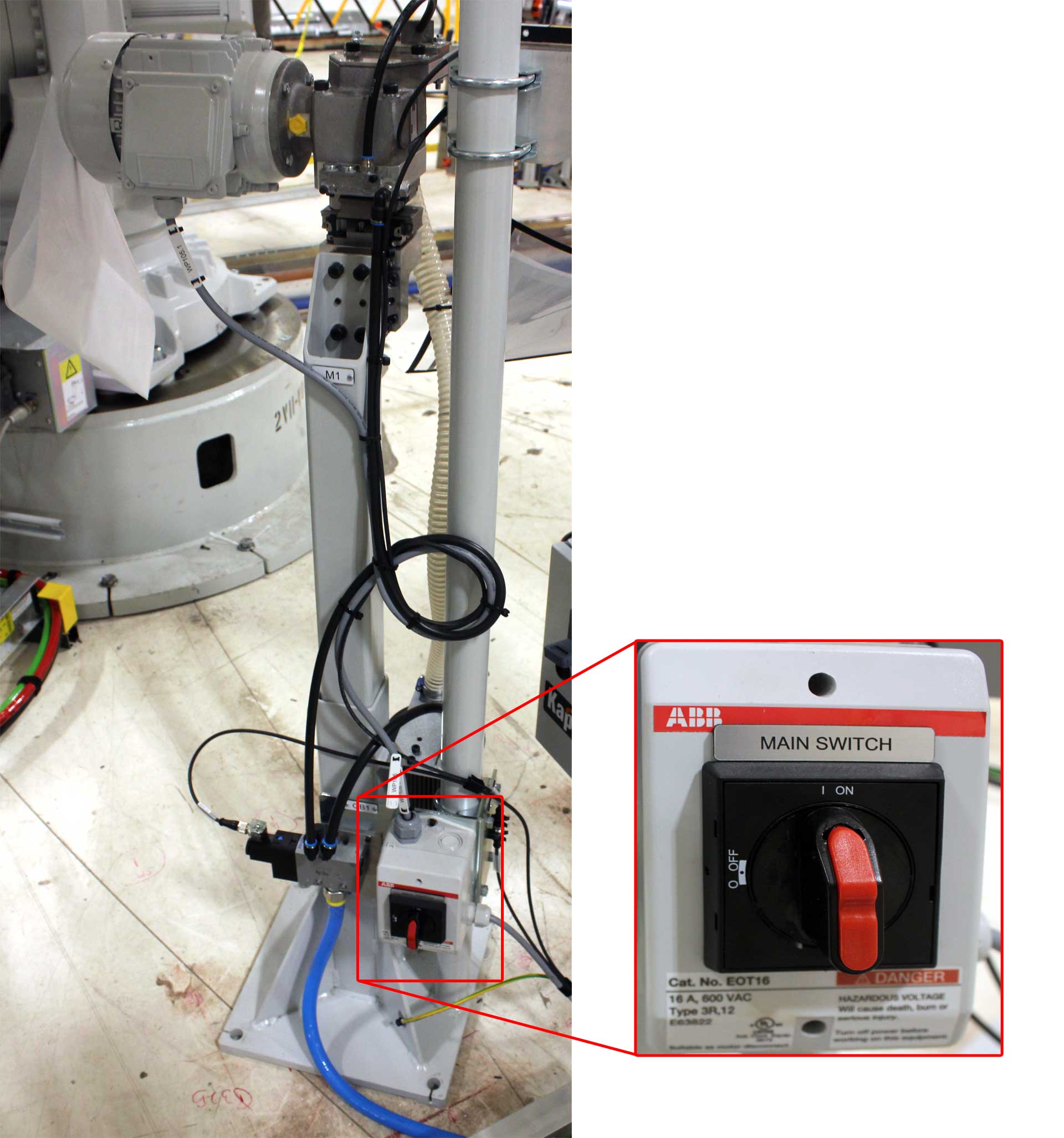
Step 6: ABB Weld Controller
- At each ABB Weld Controller, rotate the disconnect switch to the "OFF" position.

Step 7: IRC5 Robot Controller Single Cabinet
- At each ABB IRC5 Robot Controller, rotate the Main Power Selector Switch to the "OFF" Position.

Step 8: Weiss Variable Frequency Drive (VFD) Controller
- At the Weiss Variable Frequency Drive (VFD) Controller, rotate the disconnect switch to the "OFF" position.

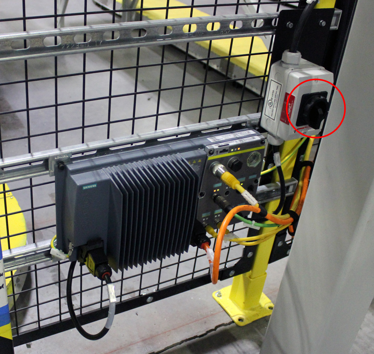
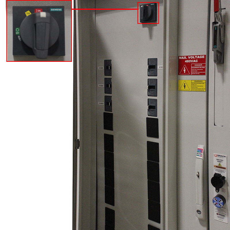
Step 9: Siemens VFD Module
- At the Siemens VFD Module, rotate the disconnect switch to the "OFF" position.
Step 10: Power Distribution Panel (PDP)
- At the Power Distribution Panel (PDP), place the Main Electrical Disconnect switch to the "OFF" position.

Step 11: Power Distribution Panel (PDP) Uninterrupted Circuits (E2)
- If control power needs to be shut off, open the Power Distribution Panel (PDP) door.
- Rotate the uninterrupted power rotary switch to the "OFF" position.
Step 12: Brauer Systemtechnik Cap Changers
- At each Brauer Systemtechnik Cap Changer, place the rotary disconnect to the "OFF" position.

Step 13: ABB Tip Dresser
- At each ABB Tip Dresser, place the rotary disconnect to the "OFF" position.