Siemens Variable Frequency Drive Modules
General
The Variable Frequency Drive (VFD) Modules receive AC from the Power Distribution Panel. The VFD Panel then supplies the required power to a device, such as a trunnion or conveyor system. There is one (1) VFD located on the 2V02 Underbody Structure Cell.
Some of these units are equipped with a disconnect switch that will remove all power from the VFD module. This is not on all of the modules through-out the line, but those that have it will have the switch located directly next to it.
| Item | Description | Function |
|---|---|---|
| A | Disconnect Switch | Rotary Disconnect switch that will remove power from the VFD module and associated equipment. |
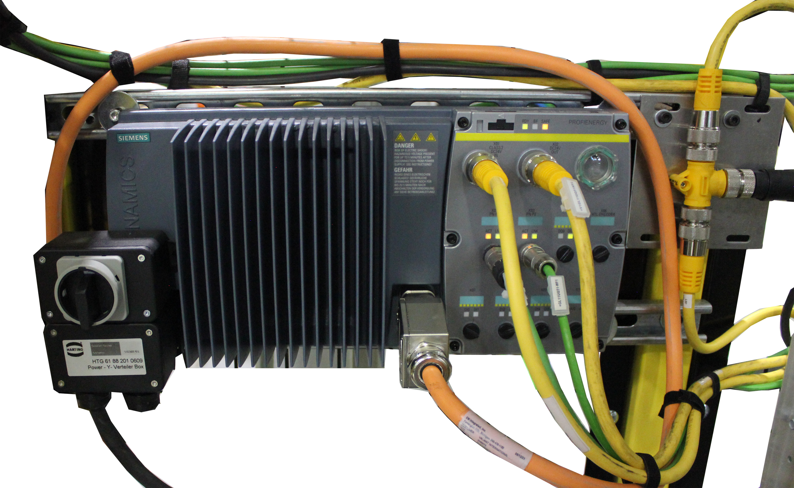
Major Components
The Siemens Variable Frequency Drive Modules features the following components.
| Item | Description | Function |
|---|---|---|
| A | PE Grounding Terminal | Connection point for grounding the unit and motor for safety and electromagnetic compatibility. |
| B | Main Supply Connection | Connection for three-phase AC power. |
| C | Motor, Brake, and Temperature Sensor Connection | Connector that holds the sensor wiring for each of these
system:
|
| D | Optical Interface | For Operator Panel IOP handheld. This allows communication between the unit and other control systems, such as PLCs or other automation systems. |
| E | Converter Status LEDS | Visual indicators for the following:
|
| F | 24 VDC In and Out | Connectors to received 24 VDC supply power and sending 24 VDC out to other devices. |
| G | USB PC Connector, Address, and PROFIBUS Termination Switch | Connection location for a PC, address and the termination switch for the PROFIBUS. |
| H | Fieldbus In and Out | For PROFINET or PROFIBUS communication. |
| I | Digital Outputs 0 and 1 with LED | Digital outputs that can be configured and programmed to perform various functions based on the application. Outputs are often used for status indication, alarm signaling, and device controls. |
| J | HTL Encoder Connection | Connector used to interface with an HTL encoder. HTL is a type of encoder signal that operates with a high voltage threshold. The HTL encoder is typically used for position feedback, closed-loop operations, high noise immunity, and reliability in harsh environments. |
| K | Digital Inputs 0 - 6 with LED | Digital inputs that can be configured and programmed to perform various functions based on the application. Inputs are used for start/stop commands, speed reference signals, fault reset, emergency stop, and interlocking. |
| L | SSI Encoder Connection | The SSI is a serial communication protocol sued to transmit position data from encoders to control systems. This connection provides accurate position feedback to the converter, closed-loop operations, dynamic positioning and error detection. |

