Main Operator Panel (MOP) Screens
Overview Screen
The Overview Screen is used as a Main Screen to select other screen for operating or monitoring the systems. In the center of the screen, the 2V02 Underbody Structure layout is displayed with various status indicators that allow personnel to quickly identify the status of each piece of equipment.
At the top of the screen, there are function buttons that allow for personnel to navigate to other available Main Operator Panel (MOP) screens. From the Navigation Bar, personnel can perform a fault reset, view the status of the Emergency Stop (E-Stop) buttons, Safety Gates, and Light (Beams) Screens. The Menu button opens the Operating Mode Screen (Auto, Manual, Dryrun, and Empty Out) and also can navigate to the All Robots Screen, return to the previous screen, view the alarm page, and view the alarm log.
| Item | Description | Function |
|---|---|---|
| A | Navigation Bar | Allows for personnel to quickly identify the status of various devices and navigate to the other available MOP Screens. |
| B | Menu Shortcuts | Allows for personnel to quickly access specific screens related to different equipment on the 2V02 Underbody Structure Cell. |
| C | System Layout | Displays entire 2V02 Underbody Structure Cell layout. |
| D | Status Indicators | Displays the status if the equipment is in the faulted or OK status condition. |

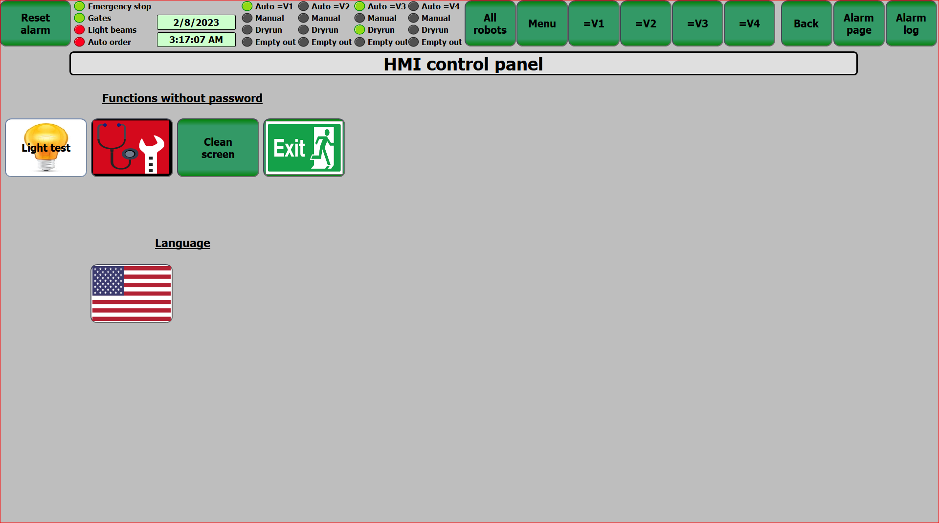
Main Operator Panel (MOP) Screen
The MOP Screen allows for personnel to perform a Light Test, Perform a System Diagnostic Test, Clean the MOP Screen, Exit the MOP software, and change the language of the software.
| Item | Description | Function |
|---|---|---|
| A | Light Test | Performs Light Test. NOTE: Button must be pressed again to turn off. |
| B | System Diagnostic | MOP Screen that identifies any problems with the MOP software. |
| C | Clean Screen | Locks the MOP Screen for cleaning and prevents any accidental button presses. |
| D | Exit MOP Software | Closes MOP Software. |
| E | Language | Changes the language displayed on all screens. |
| F | Navigation Bar | Allows for personnel to quickly identify the status of various devices and navigate to the other available MOP Screens. |
Operating Mode Screen
The Operating Mode Screen allows for personnel to switch between the available operating modes The Operating modes include Automatic Mode, Automatic Step Mode, Manual Mode, Dry Run, Empty Out, and Cycle Stop.
Above the function buttons, there are status indicators that help assist personnel in identifying the status of the stations, Air Supply, Safety Conditions, if all robots are in the Home position, and if the zone is empty. This screen is accessed by pressing the "Menu" button in the Navigation Bar on any screen.
| Item | Description | Function |
|---|---|---|
| A | Status Indicators | Used to quickly identify the status of the equipment in the 2V02 Underbody Structure Cell. |
| B | Automatic Mode | Automatic Mode of Operation allows for the equipment to continuously run until either blocked or starved of parts. |
| C | Automatic Step Mode | Automatic Step Mode allows for the system to run in Automatic Mode but only performs one step at a time. |
| D | Manual Mode | Manual Mode of Operation allows for personnel to manually control and actuate pieces of equipment by using the Manual Function Screens. The Manual Mode functions on the MOP screens cannot be used until the 2V02 Underbody Structure Cell is placed into manual mode. Manual Mode is NOT a normal means of production and is primarily used for maintenance and troubleshooting purposes. |
| E | Dry Run | Dry Run allows for the 2V02 Underbody Structure Cell to run with no parts being processed. |
| F | Empty Out | Empty Out allows for the 2V02 Underbody Structure Cell to complete the required operations to finish the cycle and return to the Home position. |
| G | Cycle Stop | Cycle Stop allows for the equipment to finish its current cycle and then return to the Home position. |
| H | Navigation Bar | Allows for personnel to quickly identify the status of various devices and navigate to the other available MOP Screens. |

Alarm Screen
The Alarm Screen will display any current and active faults that have occurred with the 2V02 Underbody Structure Cell. The Alarm Screen will also display the number, the date and time the fault occurred, the status of the fault, and a description to help inform the operation to locate and rectify the fault.
After the fault has been rectified, use the "Reset Alarm" button in the upper-left hand corner of the screen to clear the fault from the screen and reset the safety circuit. The cleared alarm will then appear in the Alarm Log Data Bank. Use the "Alarm Log" button in the upper-right hand corner of the screen to navigate to the Alarm Log Screen.
| Item | Description | Function |
|---|---|---|
| A | Alarm Number | Number value associated with alarm. |
| B | Alarm Time and Date | Displays the time and date of when the fault occurred. |
| C | Alarm Status and Text | Displays the current status of the fault (active, inactive, etc.), as well as a brief description of fault that has occurred. |
| D | Reset Alarm | Clears all remedied faults and resets safety circuit. All remedied faults are moved to the Alarm Log Data Bank. |
| E | Navigation Banner | Allows for personnel to quickly identify the status of various devices and navigate to the other available MOP Screens. |

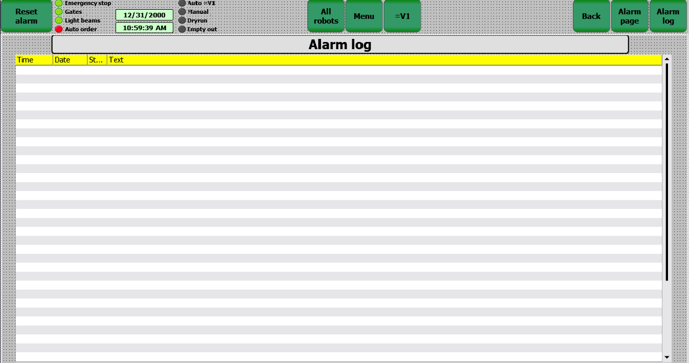
Alarm Log Screen
The Alarm Log Screen will display all of the alarms cleared from the Alarm Screen with the latest alarms listed at the top. Use the scroll bar on the left side of the screen to scroll either up or down to view the faults.
The Alarm Log Screen will categorize the Alarms by Time and Date, Status, and Message.
| Item | Description | Function |
|---|---|---|
| A | Date and Time | Displays the current date and time the alarm occurred. |
| B | Status | Displays the current status of the alarm. |
| C | Message / Text | Provides a brief description of fault that occurred. |
| D | Navigation Bar | Allows for personnel to quickly identify the status of various devices and navigate to the other available MOP Screens. |
All Robots Screen
The All Robots Screen allows for personnel to identify the status of each robot used in the 2V02 Underbody Structure Cell. Using Robot Status function buttons, personnel will navigate to the specific Robot Status Screen.
At the bottom fo the screen, there are function buttons that allow personnel to send the robots to the Weld Gun Check Position, send all robots to the Tip Changer, send all robots to the Service Position, send all robots to the Tip Dressers, perform test on the Weld Guns, and send the robots to the TCP Check position.
| Item | Description | Function |
|---|---|---|
| A | Robot Status | Function buttons that navigates to the Robot Status Screen. |
| B | Robot to Weld Gun Check | Function button that sends the robot to the Weld Gun Check position. |
| C | Robot to Tip Change | Sends Robot to associated Tip Changer. |
| D | Robots to Service with(No Tool) | Sends Robot to the Service Position with no tool equipped. |
| E | Robots to Tip Dress (Global) | Sends all robot to associated Tip Dresser. |
| F | Robots to Tip Dress | Sends applicable robots to the associated Tip Dresser. |
| G | Test Weld Gun | Sends all robots to test weld guns. |
| H | Robots to TCP Check | Sends robots to TCP check position. |
| I | Navigation Bar | Allows for personnel to quickly identify the status of various devices and navigate to the other available MOP Screens. |

General Robot Status Screen
The General Robot Status Screen displays detailed status information regarding the selected robot.
From this screen, personnel can view the status of the interlocks, overall status of the robot, signals from the robot, signals to the robot, and digital signals to the robot.
In the top left corner of the screen, there are four (4) help function buttons that will navigate personnel to the associated page.
| Item | Description | Function |
|---|---|---|
| A | Help Function Buttons | Navigates users to applicable help pages. |
| B | Interlocks | Displays the status of the robot's interlocks. |
| C | Robot Status | Graphic representation of robot and status.
RED = NOT OK | YELLOW = Warning | Green = OK |
| D | Signals from Robot | Displays the signals that are output from the robot. |
| E | Digital Signals from Robot | Displays the digital signals that are output from the robot. |
| F | Signals to Robot | Displays the signals sent to the robot. |
| G | Digital Signals to Robot | Displays the digital signals sent to the robot. |
| H | Navigation Bar | Allows for personnel to quickly identify the status of various devices and navigate to the other available MOP Screens. |

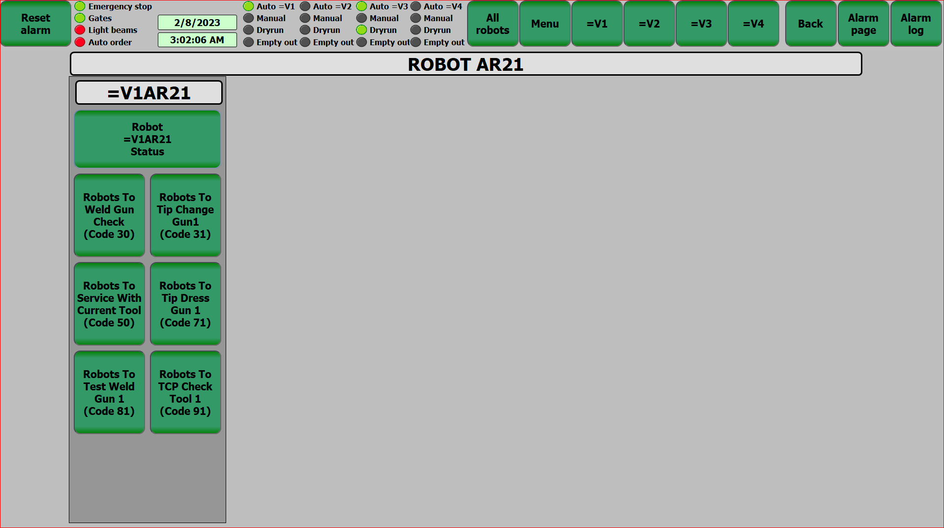
Manual Robot Screen
The Manual Robot Screen displays various function buttons to manually control the robots within the 2V02 Underbody Structure Cell.
From this screen, personnel can navigate to the specific Robot Status Screen for each individual robot, send the robot to the Weld Gun Check Position, send the robot to the Tip Changer, send the robot to the the Service Position with the Current Tool, send the robot to the Tip Dresser, perform a test of the Weld Gun, and send the robot to the Tool Center Point (TCP) Check position as well as perform a Validation Service.
| Item | Description | Function |
|---|---|---|
| A | Robot Status | Function buttons that navigates to the Robot Status Screen. |
| B | Robot to Weld Gun Check | Function button that sends the robot to the Weld Gun Check Position. |
| C | Robot to Tip Change | Sends the selected robot to associated Tip Changer. |
| D | Robot to Service with Current Tool | Sends the selected robot to the Service Position with the Current Tool equipped. |
| E | Robots to Tip Dress | Sends the selected robot to the associated Tip Dresser. |
| F | Test Weld Gun | Selected robot performs Weld Gun Test. |
| G | Robots to TCP Check | Sends the selected robot to TCP Check position. |
| H | Navigation Bar | Allows for personnel to quickly identify the status of various devices and navigate to the other available MOP screens. |
Part Tracking Screen
The Part Tracking Screen allows for personnel to view the current position of each model being processed through the 2V02 Underbody Structure Cell. In the center of the screen, the system layout displays the Geo Fixture or Tool at the load position. On the right side of the screen, there are function buttons that will navigate users to the Detailed Part Tracking page, displaying the ID Number, Serial Number, Operation Code, Destination, Part Present Sensors, and other detailed information.
| Item | Description | Function |
|---|---|---|
| A | Function Buttons | Navigates user to Detailed Part Tracking Screen. |
| B | Tool Position | Displays the current position of the specific tooling. |
| C | Navigation Bar | Allows for personnel to quickly identify the status of various devices and navigate to the other available MOP Screens. |
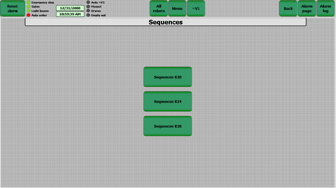
Sequence Screen
The Sequence of Operations Screen displays the current and active step for the selected piece of equipment. On the right side of the screen, personnel can use the function buttons and view the Sequence Help Page. At the bottom of the screen, there is a "Reset Sequence" button that will cancel the current operations and return the equipment to the Home position.
| Item | Description | Function |
|---|---|---|
| A | Navigation Bar | Allows for personnel to quickly identify the status of various devices and navigate to the other available MOP screens. |
| B | Sequence Buttons | Allows for personnel to select a specific sequence for the 2V02 Underbody Structure Cell. |
| C | Help Screen | Navigates User to the Sequence Help Page. |
| D | Active Step | Displays current step number and description of what is being performed. |