Power Up From All Sources Off
Cell Power Up Notation
The following procedure covers the power up of the 2V10 Bodyside RH Cell when the cell has been completely powered down. This procedure provides full power up instruction for the cell and readies the cell for automatic mode of operation. The nature of the cell's "Power Up Procedure" will be conditioned by the manner in which the previous cycling was terminated. In actual operation, some steps may only need to be verified.
Make sure the Pre-Start Check procedure has been performed!
Remove and clear any lockouts throughout the 2V10 Bodyside RH Cell. Follow procedures outlined in the Lockout / Tagout (LOTO) Placards posted on the Power Distribution Panel.
Follow all plant guidelines and regulations for start-up safety. Follow all safety warning labels posted on the equipment. Refer to the Lockout / Tagout (LOTO) placard for energy source locations. Failure to comply could result in severe personal injury or death, and/or equipment damage.
Allow only personnel with appropriate training and experience to operate or service the equipment. The use of untrained or inexperienced personnel to operate or service the equipment can result in injury, including death, to themselves and others, and/or damage to the equipment.
Step 1: ABB Tip Dresser
- At each ABB Tip Dresser, place the rotary disconnect to the "ON" position.
Step 2: Brauer Systemtechnik Cap Changers
- At each Brauer Systemtechnik Cap Changer, rotate the disconnect switch to the "ON" position.

Step 3: Pedestal Sealer Stand
- At each Pedestal Sealer Stand, place the Oil Switch in the "ON" position.

Step 4: Safety Gates
- Before closing the safety gate, ensure there are no personnel within the cell performing maintenance, repairs or troubleshooting the equipment. Ensure all tools, carts, rags, etc. are removed from the work area.
- After all personnel have exited the work area, close and latch the safety gate.

Step 5: Power Distribution Panel (PDP) Uninterrupted Circuits
- If control power had been shut off, open the Power Distribution Panel (PDP) and rotate the uninterrupted power rotary switch to the "ON" position at each PDP.
- Close and latch the PDP door.
Step 6: Power Distribution Panel (PDP) Main Disconnect
- Power on each Power Distribution Panel (PDP) by placing the Main Electrical Disconnect switch to the "ON" position.

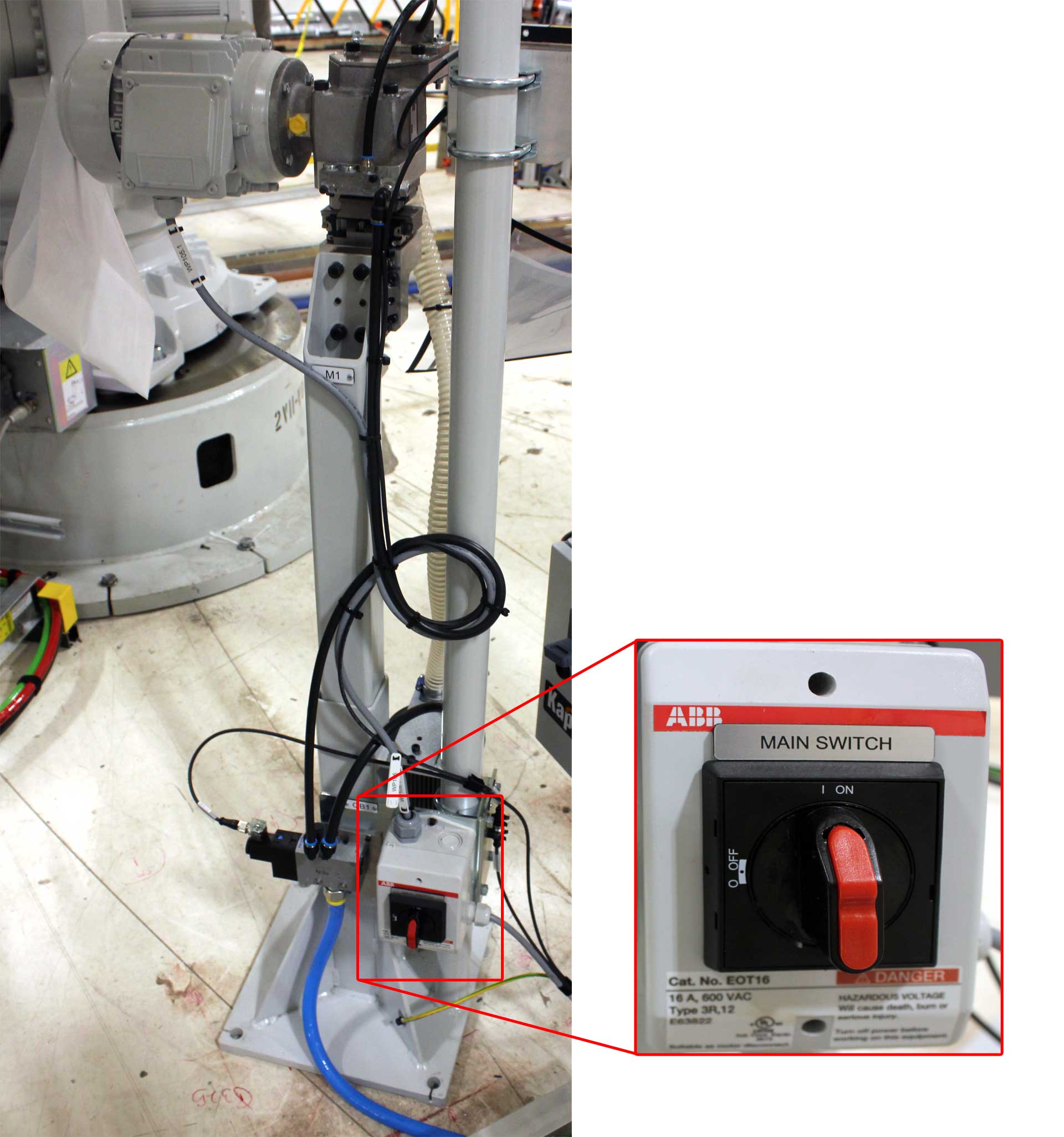
Step 7: ABB IRC5 Robot Controller Single Cabinet
- At each ABB IRC5 Robot Controller, rotate the Main Power Selector Switch to the "ON" position.

Step 8: ABB Weld Controller
- At each ABB Weld Controller, rotate the disconnect switch to the "ON" position.

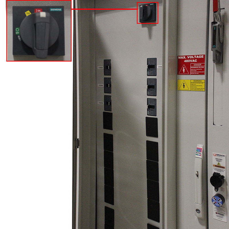
Step 9: Siemens VFD Module
- At each Siemens VFD Module, rotate the disconnect switch to the "OFF" position.

Step 10: Atlas Copco Sealer Controller
- At each Atlas Copco Sealer Controller, place the Main Switch rotary disconnect in the "OFF" position.

Step 11: ABB Transformer Neutral Panel
- At each ABB Transformer Neutral Panel, place the Main Switch rotary disconnect in the "OFF" position.
Step 12: ABB Integrated Dispensing Connector (IDC)
- At each IDC, place both of the Main rotary disconnect and Heat rotary disconnect in the "OFF" position.

Step 13: ABB Dual Drum Media Supply Systems and Controllers
- At each ABB Media Supply System and Controller, ensure that controller is placed into the "EXTERNAL" position (turn to the right) on the Key Switch.
- Ensure that the Emergency Stop (E-Stop) buttons are reset.

Step 14: Tucker TE1500 Stud Controllers
- At each TE1500 Stud Controller, place the rotary disconnect to the "ON" position.

Step 15: Main Air Distribution Panel
- At the Main Air Distribution Panel, rotate the safety lockout valve to the "OPEN" position.
- On the pressure regulator unit, verify the incoming air is set to the safe, required operating pressure.

Step 16: Ancillary Air
- At the Station Level Air Distribution Panels (or Ancillary Air Panels) Place the Safety Lockout
Valve to the "OPEN" position.
- On the pressure regulator or digital pressure switch, verify the incoming air is set to the safe, required operating pressure
- Ancillary air panels are located at many locations, including turntables, robots, data scribe, and the ABB Drum Media Supply Systems.


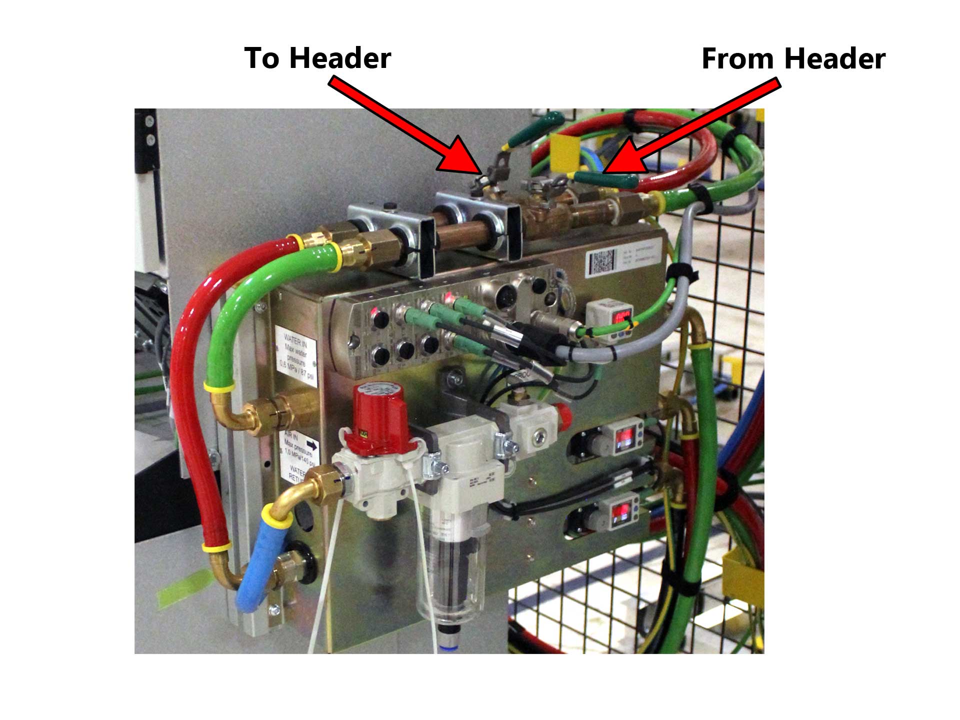
Step 17: Water System
- Place the Plant Water In Ball Valve to the "OPEN" position.
- Place the To Header Ball Valve to the "OPEN" position.
- Place the From Header Ball Valve to the "OPEN" position.
- Place the Plant Water Out Ball Valve to the "OPEN" position.
- On each ABB Weld Controller, place the To Header and From Header Ball Valves to the "OPEN" position.

Step 18: Main Operator Panel (MOP) - Alarm Screen
- At the Main Operator Panel (MOP), view the Alarm Screen for any faults that have occurred with the 2V10 Bodyside RH Cell.
- If any faults have occurred, locate and rectify the fault.
- Press the "Reset Alarm" button in the top-left corner of the screen to clear the faults from the Alarm Screen. If the Alarm Screen indicates there are still faults within the cell, continue rectifying the faults until all faults have been corrected.

Step 19: Main Operator Panel (MOP) - Start Auto Button
- After all faults have been corrected, place the two-position selector switch into the "AUTO" position.
- Press and hold the "Start auto" pushbutton for four (4) seconds. The alarm horn will sound alerting personnel that the 2V10 Bodyside RH Cell is entering Automatic Mode of Operation.
