Controls and Indicators
Main Operator Panel (MOP)
The Controls and Indicators for the Main Operator Panel (MOP) are as follows.
| Item | Description | Function |
|---|---|---|
| A | Operator Emergency Stop (E-Stop), Work, and Home Buttons | Allows for personnel to immediately stop all machine motion, actuate the equipment and moving it to the Work Position, or allows for personnel to return the equipment to the Home Position. |
| B | Operator E-Stop Reset, Enable Power, Start Auto, and Mode Selector Switch | Allows for personnel to reset the safety circuit after pressing an E-stop, start the equipment in Automatic Mode, informs personnel that enabling power is provided to the machine, and allows for personnel to place the system in either Automatic Mode or Manual Mode. |
| C | MOP Display | The MOP Display provides the accessible screens for the 2V03 Underbody Floor Skin Cell. From these screens, personnel can make adjustments, reset a fault, or perform manual functions. |

Secondary Operator Panel (SOP)
The Zone Controlling Secondary Operator Panel (SOP) panel allows for personnel to control, adjust, or view the status of the equipment within one of the four zones in the 2V03 Underbody Floor Skin cell. The zone controlling SOP panel features a Siemens Simatic touch screen display, as well as three buttons to place zone zone’s equipment into the work position (green button), zone’s equipment to the home position (yellow button), or initiate automatic mode (white illuminated button).
| Item | Description | Function |
|---|---|---|
| A | Display | Touchscreen interface and displays available SOP screens for controlling and viewing the status of the zone’s equipment. |
| B | Work Pushbutton | Green button that sends the zone’s equipment into the Work position. |
| C | Home Pushbutton | Yellow button that returns the zone’s equipment into the Home position. |
| D | Start Auto Pushbutton | White illuminated button that initiates the zone’s equipment into automatic mode of operation. |
| E | Emergency Stop (E-Stop) Button | Stops all machine motion when pressed in. |

Operator Display Panel (OD)
The Operator Display (OD) Panel is a Siemens Touch Screen interface that allows for the system operator to control and monitor the status and conditions of the equipment.
| Item | Description | Function |
|---|---|---|
| A | Operator Display | Touch Screen display that allows for personnel to view and monitor the station equipment. |

Operator Stack Light
The Operator Stack Light is used to signal and inform the operator of the current status of the 2V03 Underbody Floor Skin Cell. The Controls and Indicators for the Operator Stack Light are as follows.
| Item | Description | Function |
|---|---|---|
| A | Alarm Horn | Alerts personnel that the system is starting in Automatic Mode of operation. |
| B | Red Lens | Illuminates red when a fault has occurred with the 2V03 Underbody Floor Skin Cell. |
| C | Yellow Lens | Informs personnel that a warning has occurred with the 2V03 Underbody Floor Skin Cell. |
| D | Green Lens | Informs personnel that the 2V03 Underbody Floor Skin Cell is running in Automatic Mode of Operation. |
| E | Blue Lens | Informs personnel that a model change has occurred. |

Operator Run Bar
The Controls and Indicators for the Operator Run Bar are as follows.
| Item | Description | Function |
|---|---|---|
| A | Emergency Stop (E-Stop) Button | Stops all machine motion regardless of position in sequence when pressed. |
| B | Cycle Start Button | Optical Touch Button that allows for the operator to begin the sequence in Automatic Mode of Operation. |

ABB Weld Controller
The Controls and Indicators for the ABB Weld Controller are as follows.
| Item | Description | Function |
|---|---|---|
| A | Disconnect Switch | Supplies and Removes power to the applicable weld gun. |

ABB IRC5 Robot Controller Control Panel
| Item | Description | Function |
|---|---|---|
| A | Main Power Selector Switch | This is a Selector switch that controls the main power on or main power off. The switch has provisions for placing a padlock to lockout device when in the Off position. |
| B | Emergency Stop (E-Stop) - Optional | If exists, press to immediately stop machine motion. If pressed, turn to release in the direction of the arrows. |
| C | Motors On - Optional | Illuminates when power to the servo motors are switched on and ready for program execution.
|
| D | Mode Select Key Switch - Optional | 2-position Mode key switch to select Automatic or Manual.
Set for Automatic mode for running production. Set to Manual mode for programming and setup - max. Speed is 250mm's / second (600 inches / minute). |
| E | Safety Chain LED's | Displays status and errors on the safety chain. |
| F | USB Connector - Optional | Optional port used to connect an external USB device to the controller. |
| G | Service PC Connection | Used to connect a computer to the controller. |
| H | FlexPendant Connector | FlexPendant Socket Connector. The connector must be in manual mode to use. If the system is not shut down when disconnecting the FlexPendant, it will go into an emergency stop state. |
| I | Duty Time Counter - Optional | Optional counter that keeps running time of hours of use. |
| J | Service Outlet | 115/230V 200W Service Power Outlet. |

ABB Robot FlexPendant
The Controls and Indicators for the ABB Robot FlexPendant are as follows.
| Item | Description | Function |
|---|---|---|
| A-D | Programmable Keys | Four (4) user-defined keys that can be configured to set or reset an output (for example open/close gripper) or to activate a system input. |
| E | Select Mechanical Unit | Select the mechanical unit. |
| F | Toggle Motion Mode | Toggle between Re-Orient or Linear Motion Mode. |
| G | Toggle Motion Mode | Select Axis 1-3 or Axis 4-6. |
| H | Toggle Increments | Toggle the size of increments. |
| I | Step Backward Button | This causes the program to execute one instruction backward as the button is pressed. |
| J | Start Button | Start the program execution |
| K | Step Forward Button | This causes the program to execute one instruction forward as the button is pressed. |
| L | Stop Button | Stops the program execution when the button is pressed. |
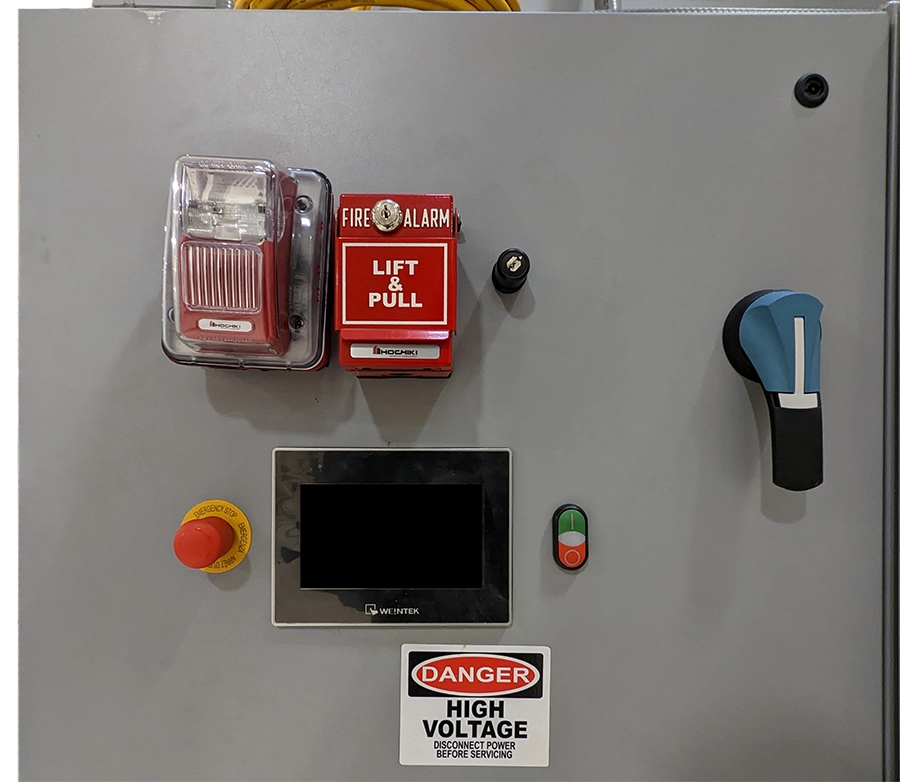
Dust Collection Control Panel
The controls and indicators for the Dust Collection Panel are as follows.
| Item | Description | Function |
|---|---|---|
| A | Fire Alarm | Activates the dust collector’s fire suppression system. |
| B | Main Electrical Disconnect Switch | Supplies or removes power from the dust collection unit. |
| C | Emergency Stop (E-Stop) Button | Stops all machine motion regardless of position in sequence when pressed. |
| D | Display Screen | Displays the status and manual controls for the dust collection system. |
| E | Start / Stop Switch | The Stop / Start switch controls the operation of the motor/blower units, in conjunction with the Variable Frequency Drive (VFD) panels. The green start button begins the collection operations while the red stop button stops the collection operation. |
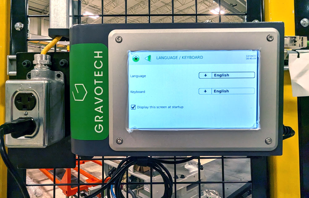
Gravotech Date Scribe Controller
The Gravotech Date Scribe Controller is designed to manage the markings performed by the numerically controlled heads. It contains the control and power electronics as well as a screen. The Control Unit is the center of the traceability system.
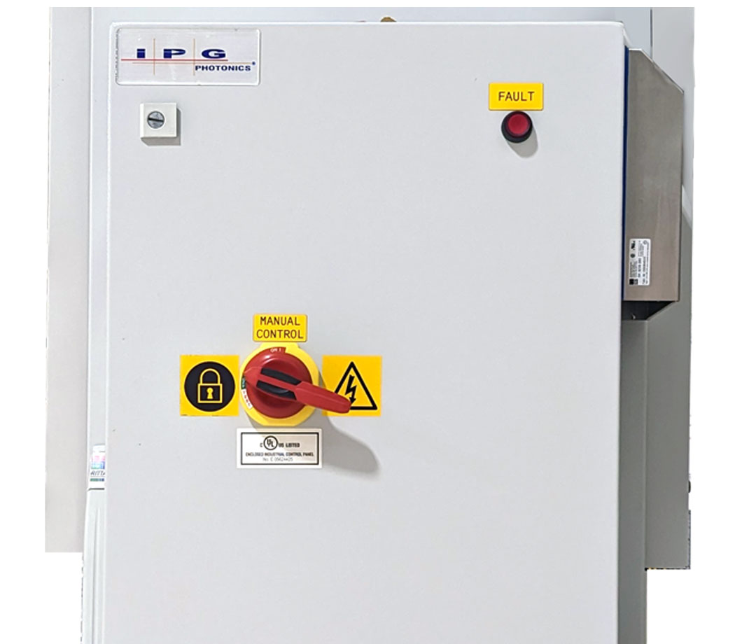
IPG Photonics Laser Chiller
The IPG Photonics Laser Chiller features the following external components.
| Item | Description | Function |
|---|---|---|
| A | Fault Button | Indicates any errors or faults that occur in the chiller's operation. Pressing the fault button resets the chiller and clears any fault codes stored in the system's memory. |
| B | Disconnect Switch | Removes power from the laser chiller if placed in the Off position and returns power to the laser chiller if placed in the On position. |
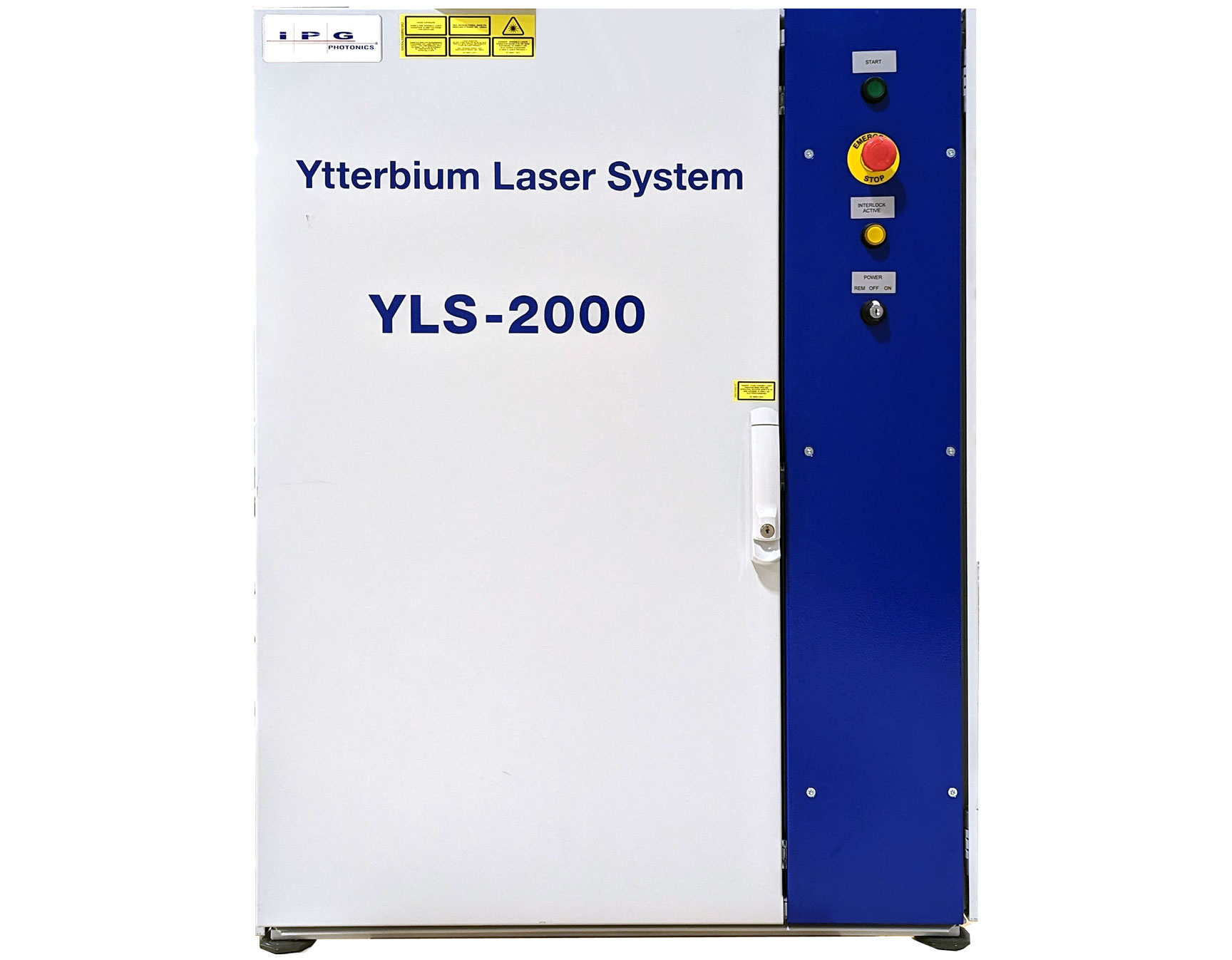
IPG Photonics High-Power Fiber Laser Resonator
The Controls and Indicators features the following components.
| Item | Description | Function |
|---|---|---|
| A | Start Button | Pressing the Start button switches on the laser modules power supplies. The start button will be illuminated when the main power supplies are On. |
| B | Emergency Stop (E-Stop) Button | Sends a E-Stop condition to the system and shuts down the entire system. |
| C | Interlock Active Indicator | Indicates whether the laser's interlock system is active or not. The interlock system is designed to prevent the laser from operating if any of the safety interlock circuits are open or if any of the safety features are not functioning correctly. |
| D | Power Key Switch | Key switch to turn the laser resonator On or Off, or place the laser resonator in Remote Mode "REM". |
Safety Gate Switch
The Controls and Indicators for the Safety Gate Switch are as follows.
| Item | Description | Function |
|---|---|---|
| A | Request to Enter | Allows for personnel to request access into the cell. When the button has been pressed, the current machine cycle will finish. After the cycle is finished, the safety gate will unlock, allowing for personnel to open the gate and enter the cell. |
| B | Gate Reset | Resets and locks the safety gate. |
| C | Emergency Stop (E-Stop) Button | The E-Stop button will interrupt machine motion in case of an emergency. The activation of the E-Stop will bring the cell to an immediate stop, irrespective of the position in the sequence. |

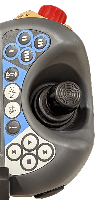
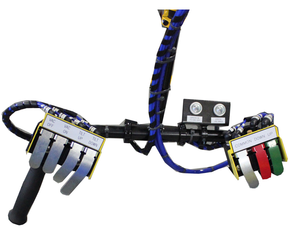
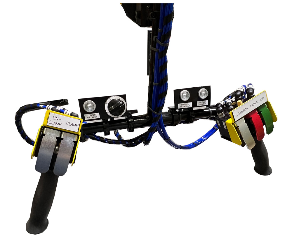
Unified Lift Assist
The Controls and Indicators for the Unified Lift Assist are as follows.
| Item | Description | Function |
|---|---|---|
| A | Vac Off | Press to turn the vacuum pressure off and release the part from the suction cups. The "GREEN OKAY TO VAC OFF" indicator must be lit. |
| B | Vac On | Press to turn the vacuum pressure on and give pressure to the suction cups to acquire the part. The "GREEN VAC MADE" should be lit once you press this button. |
| C | Tilt Horiz | Press to tilt the lift assist up to position the part into the bin or fixture. |
| D | Tilt Vert | Press to tilt the lift assist down to position the part into the bin or fixture. |
| E | Green OK To Vac Off Indicator | Lights green when the part is ready to be released to remove vacuum pressure. |
| F | Green Vac Made Indicator | Lights green when the vacuum pressure is good for part pick up. |
| G | Common | Press this button while pressing the "UP" or "DOWN" buttons. The buttons will not function without this button also being pressed. |
| H | Down | Press to lower the load assist. Must also press the "COMMON" button simultaneously. |
| I | Up | Press to raise the load assist. Must also press the "COMMON" button simultaneously. |
| J | Unclamp | Press to unclamp the lift assist and release the part to the bin or fixture. The "GREEN OK TO UNCLAMP" indicator must be lit before unclamping the part. |
| K | Clamp | Press to clamp the part onto the lift assist. |
| L | Green Ok To Unclamp Indicator | Lights green when the part is ready to be unclamped. Do not unclamp before light turns green. |
Safety Gate Switch
The Controls and Indicators for the Safety Gate Switch are as follows.
| Item | Description | Function |
|---|---|---|
| A | Request to Enter | Allows for personnel to request access into the cell. When the button has been pressed, the current machine cycle will finish. After the cycle is finished, the safety gate will unlock, allowing for personnel to open the gate and enter the cell. |
| B | Gate Reset | Resets and locks the safety gate. |
| C | Emergency Stop (E-Stop) Button | The Emergency Stop (E-Stop) button will interrupt machine motion in case of an emergency. The activation of the E-Stop will bring the cell to an immediate stop, irrespective of the position in the sequence. |